Logic (Early Access)
The Logic view allows you to create, edit, and manage Logic Models used to define the behavior and control flow of a layout. For more information, see Logic Modeling
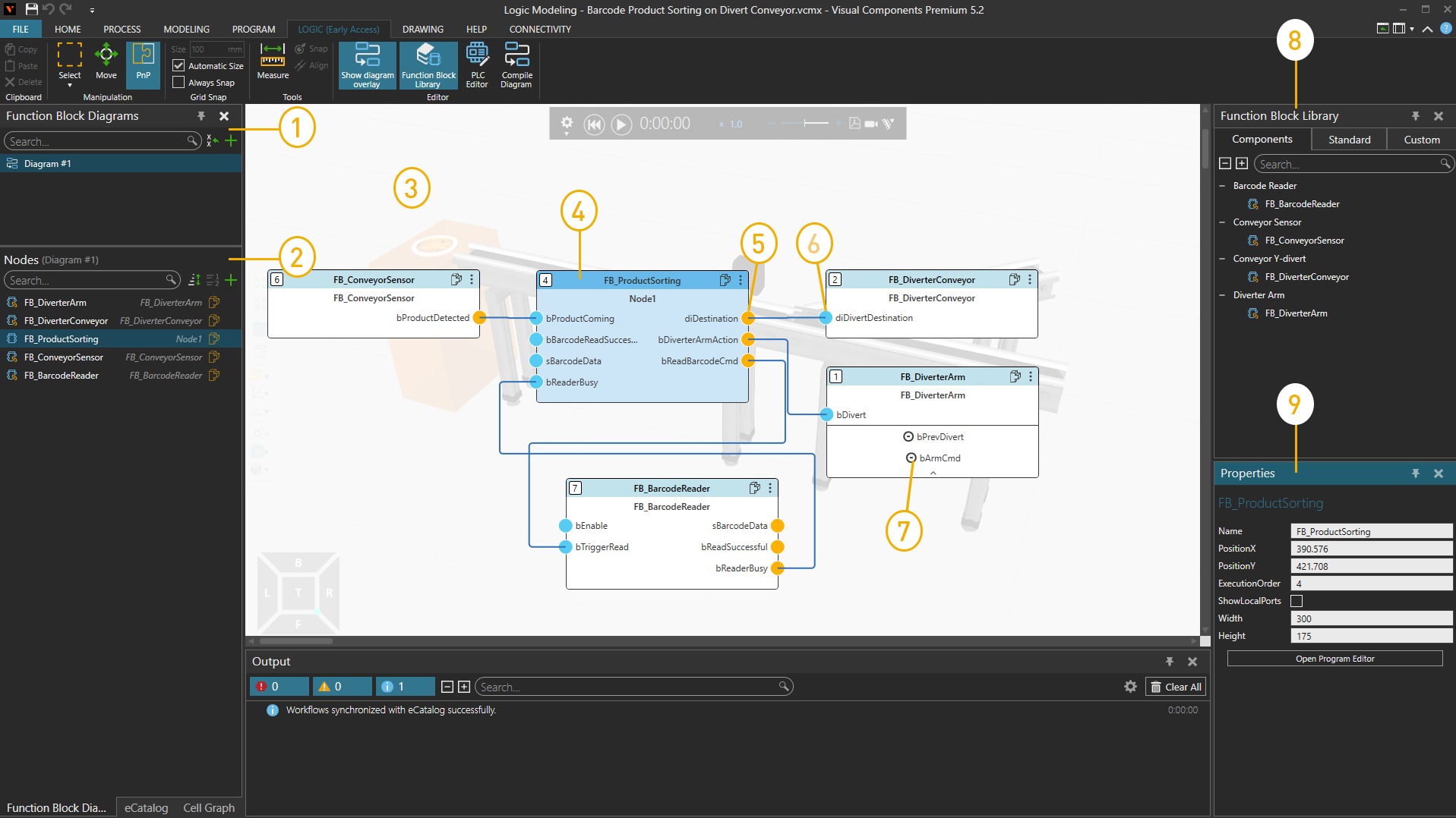
| 1. | Function Block Diagrams |
| 2. | Nodes list |
| 3. | Function Block Diagram overlay |
| 4. | Selected Node |
| 5. | Output port |
| 6. | Input port |
| 7. | Local port |
| 8. | Function Block Library |
| 9. | Properties panel |
Access
To access the Logic view:
- Click the Logic tab.
Panels
The Logic view shows, by default, the following panels:
- Function Block Diagrams for creating, organizing, and editing function block diagrams in a logic model. The panel itself consists of two panes. The top pane (Diagram Tree) shows all function block diagrams in the logic model and allows you to create, rename, delete, search and organize diagrams. The bottom pane (Nodes) shows the nodes and function blocks contained in the selected diagram and allows you to select and manage logic elements.
- eCatalog for browsing connected sources of files and adding them to a layout.
- Cell Graph for listing, selecting and editing components in a layout.
- Properties for reading and writing properties of selected objects in a component. This includes nodes, behaviors and features. Component properties are objects with their own set of properties listed in a Property task pane.
Context
The context of the Logic view is logic model configuration.
You can:
- Create and edit function block diagrams.
- Add and configure function blocks.
- Define connections between logic nodes.
- Organize logic models into reusable structures.
- Develop PLC programs.
- Compile and validate logic models.
- Test logic behavior during simulation.
Commands
By default, the following commands are shown in the Ribbon when you click the Logic tab.
| Name | Description |
| Copy | Copies the current selection to the clipboard. |
| Paste | Adds the contents of clipboard to active area or field of workspace depending on data type. |
| Delete | Deletes the current selection. |
| Select | Allows for direct and indirect selection of features in the 3D world using listed commands.
Rectangular selection Free-form selection Select all Invert selection |
| Move | Allows a selected object to be moved along an axis or plane, rotated around an axis, and snapped and aligned to a point in 3D world. |
| PnP (Plug and Play) | Allows components to me moved and snapped together to form physical connections in the 3D world. |
| Size | Defines the interval for snapping a selected object along an axis or plane when using the manipulator. |
| Automatic Size | Turns on/off the automatic calculation of intervals for snapping a selected object along an axis or plane when using the manipulator. |
| Always Snap | Turns on/off the automatic snapping of a selected object along an axis or plane at intervals when using the manipulator. |
| Measure | Measures the distance and/or angle between two points in 3D world. Additional options are displayed in a task pane.
Mode Settings Snap Type Tip: The results of a measurement are sent to Output panel. |
| Snap | Allows a selected object to be snapped to a location in 3D world by using one to three points. Additional options are displayed in a task pane.
Mode Settings Snap Type |
| Align | Aligns a selected object using two points. Additional options are displayed in a task pane.
Settings Snap Type |
| Show diagram overlay | Shows or hides the Function Block Diagram overlay. |
| Function Block Library | Shows or hides the Function Block Library panel used for browsing and inserting function blocks into diagrams. |
| PLC Editor | Shows or hides the PLC Editor panel used for editing PLC source code. |
| Compile Diagram | Compiles the active logic model and reports any errors or warnings in the Output panel. |
| Restore Windows | Restores the workspace of current view to its default setting. |
| (Windows) Show | Displays a list of panels that can be shown/hidden from the current view of workspace. |